
I love hockey. My wife Jasmine also loves hockey. We love just about everything about hockey. The amazing shots. The more amazing saves. The fights. We love rooting for the Avs no matter how much they lose. We especially love the all-star break; we watch the skills competition religiously. Our favorite is probably the Skills Challenge Relay just because you get to see so many insane maneuvers perfectly executed all over the ice in just two or three minutes. That said, another challenge really caught our eye this year: the Accuracy Shooting. That's the one where targets are mounted on the four corners of a goal and players compete to see who can hit all four in the shortest time. It looks awesome, but I always wondered how they could accurately score it. I mean, the fastest time on record is just 7.3 seconds by Daniel Sedin! Human reaction time is about 0.25 seconds, so the official time could have as much as a 3% variance from the actual time. So to celebrate Pi Day, Jasmine and I decided to try to build a rig that could accurately measure times down to the millisecond.
Our design was relatively simple: instead of using those styrofoam targets the NHL loves, we would have reusable targets mounted on hinges. Each target would be hooked up to a circuit connected to a GPIO pin on the Pi. When the target was fully extended at the start of the competition, the circuit would be open. Knocking the target back would somehow close the circuit, and the Pi would know the target had been hit by registering the voltage change on the GPIO pin. Once all circuits were closed, the Pi would stop an internal timer and report the results. To build the full rig, we used the following materials:
2-1/2" Diameter U-Bolt x 8
30' or more of Cat5 Cable
A wooden 2x4 at least 24" long
Assembling the Raspberry Pi:
It's worth noting that the LCD screen and case are not strictly necessary for this build. The Raspberry Pi is a full fledged computer, and you could just as easily plug in your own screen to the onboard HDMI port and a mouse / keyboard to the USB ports. In fact, with the A/V port you could even use that old TV / VCR combo that's collecting dust in your garage as a monitor. However, since I knew I'd be transporting this project back and forth from the rink, I didn't want to haul all that clutter. Also, outlets are at a premium at my rink, so I wanted to be able to power both the Raspberry Pi and the monitor from a single plug. Fortunately, the case comes bundled with a 10cm Micro USB Splitter Cable, and the 2.4 amp power source provides plenty of juice to run both the screen and the Raspberry Pi.
As far as putting everything together, I'll say this about the fine folks at Raspberry Pi: I never cease to be amazed by how simple they make bootstrapping their machinery. Jasmine took the task of assembling the Raspberry Pi and the LCD screen in the case while I downloaded the NOOBS installer onto the SD card. They do sell SD cards that are pre-installed with NOOBS and have a nifty Raspberry Pi logo screen printed on them, but those were backordered when I was gathering supplies. Once Jasmine had wired up the screen, which was literally as simple as plugging a ribbon cable into the Raspberry Pi and the LCD screen adapter board, and I had inserted the SD card we tried booting everything up. Even before the OS was installed, the touch screen just worked. A few taps later and NOOBS had installed Raspbian. Like I said, amazingly simple.
Writing the Application:
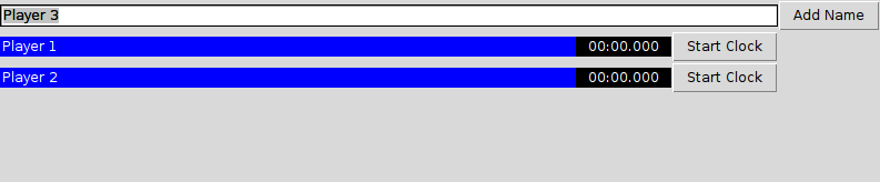
Since Raspbian comes with Python and a number of useful libraries pre-installed, we decided to use that to build our app. I won't go into the details as the source is all available from GitHub. To give a brief overview, we used RPi.GPIO to initialize the voltage output on the GPIO pins and Tkinter for building the application GUI. The user is able to enter an arbitrary number of player names, and can individually start a timer for each player. Once the clock is started, it will continue to run until each GPIO pin has been connected to a ground pin.
Interfacing with the Raspberry Pi:
When it came to interfacing with the Raspberry Pi's GPIO pins, I initially thought we should connect them to a breadboard via a Pi Wedge. I had a vision that I should be able to easily disconnect all wires from the Raspberry Pi for transportation, and then I should be able to plug everything back in without wondering, "Now does the red wire go into the fourth pin from the right, or the fifth...?" I thought having one single ribbon cable would give me that simplicity. Unfortunately, I hadn't anticipated the possibility that I could plug the ribbon cable in upside down. Here's a bizarre fact about GPIO pins: you have to use a pull up resistor to set the voltage on the pin to either high or low. Without the resistor, the pin will "float" between states depending on environmental factors. The Raspberry Pi has internal resistors for this purpose that you can set in software, which I had set for the specific pins that I planned to use. The trouble was, with the ribbon cable upside down, when I went to test the circuit I was connecting to a different set of pins that had not been initialized. The end result was that I could plug an LED into my test circuit, see it light up, unplug the LED, plug the LED back into the exact same circuit, and it wouldn't light up because the pin had floated to another state. After about two hours of infuriating attempts to debug what was happening, I realized my error with the cable. That's when I tried to unplug the ribbon cable, and discovered that the combined friction of 40 GPIO pins made it all but impossible to remove.
Once I finally pried off the ribbon and recognized that it was neither easy to remove nor foolproof, I decided to go with a smaller 6-pin jumper wire with one end stripped to plug into the breadboard. There's a run of 5 GPIO pins and a ground pin that are easy enough to find (pins 29, 31, 33, 35, 37, and 39 on a standard pinout diagram), and since the jumper wire is color coded I always know to connect the black wire to ground.
Building the Targets:
To build the targets, we took a 2x4 and cut it into 6 inch lengths. We then drilled holes to run the U Bolts through so that we could attach the assembled targets to the frame of the goal. A quick bit swap later and we drilled holes to mount the self-closing hinges, leaving enough space between to mount a piece of the magnetic door switch set. We attached the winged plates to the cooking grates using standard bolts with 1" diameter washers that could span the space between the bars on the grate. The winged plates snapped right into the hinges to form a modular design. Next we attached the wired piece of the magnetic door switch set to the 2x4 between the hinge and the U Bolt. We stuck the other piece of the magnetic door switch set to the hinge itself using the included adhesive tape so that when the hinge closed the two pieces lined up within 1cm of each other.
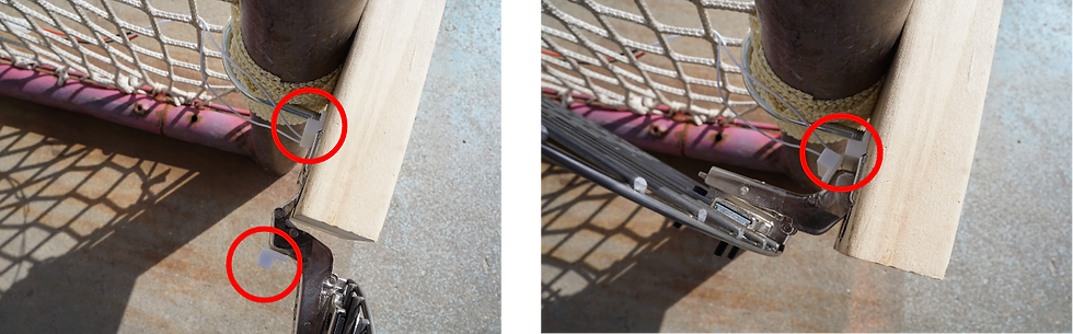
Lastly, we soldered the ends of the wires from the magnetic door switch set to one piece of the automotive jumper 2 wire assembly. To connect all of the targets to the breadboard we stripped about 5 feet of the Cat5 cable. The cool thing about Cat5 is that it's composed of four color-coded pairs of wires coiled together, so it has exactly the right number of wires to hook up all four targets. Since they're all bundled into a single cable, everything is compact and easy to transport. Are you seeing a theme in our design choices? We soldered each pair of wires to the other pieces of the automotive jumper 2 wire assemblies so that we could easily attach / unattach each target from the Cat5 cable. The other end of the cable was plugged into the breadboard to create four circuits that each ran from a GPIO pin to a magnetic door switch on the target and finally to a ground pin.
At last, we had all the components: the Raspberry Pi with LCD touch screen for controlling the system, the cable assembly to connect the Raspberry Pi with each target, and four target assemblies with magnetic switches to connect the circuits. All that was left was a little friendly competition between husband and wife...
